|
Load Relief DER Optimization
Distributed energy resources (DER) are reshaping the grid. For electric utilities, this translates into an increasingly complex ecosystem where both the regulatory landscape and the customer expectations are evolving. Also, these technology-driven changes generate new opportunities to innovate and build a grid of the future that depends less on traditional capital expenditures. The CYME Load Relief DER Optimization module equips engineers with a tool to efficiently design non-wires alternatives to mitigate capacity issues on critical grid assets.
An increasing number of utilities is being requested to systematically evaluate non-wires alternatives against traditional solutions when planning for significant capital expenditures which are essential to maintain and improve grid performance. While the engineering analyses standing behind traditional solutions have been mastered for several decades, the technical know-how required to optimally site and size utility-scale generation and energy storage systems generally remains a highly specialized expertise.
The Load Relief DER Optimization module helps engineers with the evaluation of load relief projects using battery energy storage systems (BESS) as well as dispatchable and non-dispatchable generation. The module bundles two distinct algorithms, one for the optimization of BESS and dispatchable generation and one for the sizing of non-dispatchable generation.
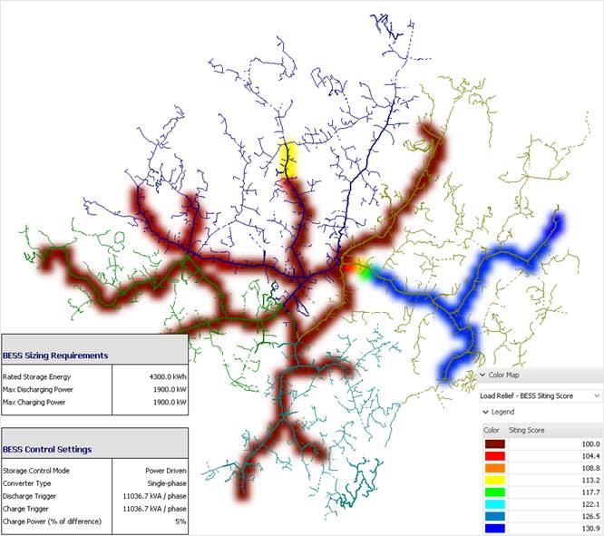
The Dispatchable DER Optimization Analysis optimally sites, sizes and sets the converter controls of BESS and dispatchable electronically-coupled generators (ECG) with the objective of reducing the loading on strategic grid assets. Simulation results unfold in a variety of outputs including summary and detailed reports, as well as heat maps highlighting optimal sites for BESS and dispatchable ECG.
The Non-Dispatchable DER Sizing Analysis determines the required generator size to mitigate assets overloads. The analysis supports up to three different types of technology simultaneously (e.g. PV, wind energy conversion system, etc.) and handles each technology's specific behavior. In terms of results, the analysis provides, for each asset experiencing an overload over the simulation period, the required active power generation to mitigate user-defined levels of overload occurrences (e.g. 70%, 95% and 99% of overload occurrences).
The Load Relief DER Optimization module turns weeks of engineering into minutes of computation and supports utilities in the modernization of their planning framework, an unavoidable step towards the alignment of their practices with the climate and clean energy goals of the 21st century.
Dispatchable DER Optimization
The primary objective of the analysis is to shave overloads at a user-defined device. Its simulation parameters include:
- An adjustable loading level target for the critical asset under mitigation
- The selection of a single-phase or three-phase converter
- The possibility to pre-select available BESS and ECG sizes
- The ability to define several BESS attributes, converter settings and lifetime parameters, such as:
- BESS minimum and maximum state of charge, efficiency, degradation, etc.
- Converter efficiency and losse
- Device lifetime and expected system load growth
- Multiple optional constraints to discard impractical installation locations
- A customizable multi-objective function for location score calculation based on new and legacy abnormal conditions
Non-dispatchable DER sizing
The primary objective of the analysis is to remove a user-defined amount of overload occurrences at each device of a network. Its simulation parameters include:
- The possibility to use different generation profiles (e.g. PV curves with and without cloud cover)
- The ability to perform the analysis for up to three different technologies or generation profiles simultaneously
- Three user-defined levels of mitigation performance (e.g. solve for 70%, 95% and 99% of overload occurrences)
Accurate BESS modeling
The BESS model is composed of many different components. The main part is the battery module that stores the active power and transfers it by charging or discharging the battery cells using internal DC/DC converters controlled by the battery management system. Power is then transferred to the AC side by the AC/DC converter. Using the capability of the converter, reactive power can be transferred in both directions, to and from the grid.
The amount of power that transits in both directions (charging/consuming and discharging/generating) is managed by the storage controller that determines, depending on its control settings and on network measurements, how much active and reactive power must be transferred to/from the network.
Several control types are supported, including power monitoring, DER monitoring and volt-var controls, to name a few.
Meaningful results at your fingertips
Beyond optimal locations, sizes and converter settings, the simulation results unfold into a variety of intuitive outputs including summary and drill-down reports, as well as heat maps highlighting the best sites for integrating BESS and dispatchable ECG.
The module can be used alone* or can leverage the power of the Steady-State Analysis with Profiles module to automatically determine the maximum energy demand and time parameters of the overloaded device.
*the CYME Distribution Analysis base package (CYMDIST) is required.
|